MAP (analogue voltage) against Injectors (petrol)
Volt/division/range: MAP sensor=2V and Injector=20V
Time/division/range: 10mSVolt/division/range: MAP sensor=2V and Injector=20V
Draw the pattern below:

Explain the operation of the sensors or Actuators using the Graph:
The MAP sensor is saying 3V running at higher RPM. When running at higher RPM, vacuum on the MAP sensor decrease and voltage will be increased. The voltage increase sending to the ECU, ECU knows the engine will be running in the higher RPM and open the injector should be longer.
RPM (Hall digital crank or distributor) against Injectors (petrol)
Volt/division/range: Injector=10V and RPM=5V
Time/division/range: 20mS
Draw the pattern below:
Running idle:

Revving Up:

When we revv-up the engine, frequency getting short and voltage getting higher. Means the engine running rich mixture and the injector open longer, rotation on the engine automatically running faster. The inductive pick up in the RPM sensor on distributor, spinning of the pick up coil running faster too due the engine running faster.
Oxygen sensor against Injectors (petrol)
Volt/division/range: Injector=10V and O2=0.5VTime/division/range: 2mS
Draw the pattern below:
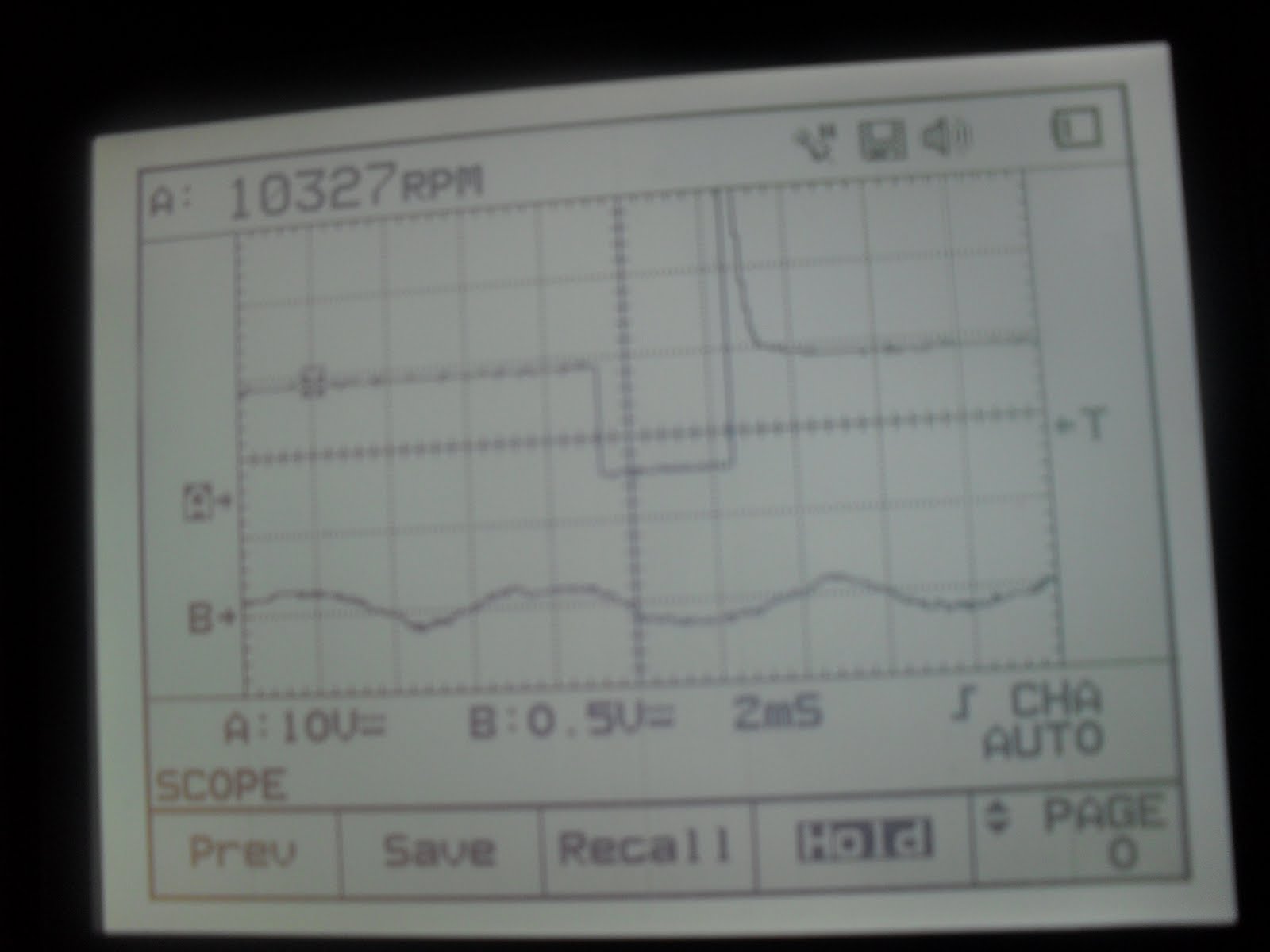
Explain the operation of the sensor or Actuator using the Graph:
Open injector effect to the engine running rich or lean. When engine running rich mixture, the peak to peak pattern of oxygen sensor will maximum reach 0.9V at the time injector open longer, and opposite if the injector open short oxygen sensor tell us running lean the voltage only 0.1V. The pattern above is saying oxygen sensor at 0.4V roughly that the injector start open longer until close loop. After the engine have a load, oxygen sensor send signal to ECU to command to the injector open longer.
Ignition primary against Injectors (petrol)
Volt/division/range: Injector=10V and Ignition=20VTime/division/range: 5mS
Draw the pattern below:

Explain the operation of the sensor or Actuator using the Graph:
Relationship between the primary ignition and injector where the ignition is set to open and close the injector to spray petrol into the combustion chamber. When we accelerate, the injector open time longer so that the engine speed automatically increase the signal sent to ECU. And ECU adjust ignition timing.
Ignition primary voltage against Ignition primary current
Volt/division/range: Ignition voltage=20V and Ignition Current=0.5VTime/division/range: 2mS
Draw the pattern below:


Explain the operation of the sensor or Actuator using the Graph:
The current clamp was setting to 20A (100mV/A) which mean maximum from the pattern 0.475V=475mV base on 100mV/A; 475mV/100mV/A=4.75A. So the current on the ignition primary was 4.75A. When the magnetic filed charge up by closing circuit to the ground, the current start flowing in the primary winding. And the current start fill up the capacitor to build up the voltage reach around 300V and the current stop; release the voltage at that time firing voltage happen and then circuit open magnetic collapse. When the voltage drop to the ground or we call dwell time, the current start to charging up.
Ref:
http://mgaguru.com/mgtech/ignition/ig108.htm
Your RPM (Hall digital crank or distributor) against Injectors (petrol) pattern is not hall but inductive.
ReplyDeleteIgnition primary voltage against Ignition primary current pattern the coil doesn't have a capacitor but the coil winding them selves store the energy look at Faraday's law
Nice to be visiting your blog again, it has been months for me. Well this article that i've been waited for so long. I need this article to complete my assignment in the college, and it has same topic with your article. Thanks, great share. Car Division
ReplyDelete